Kerf Compensation
Kerf Compensation Explained: Get Perfect-Fit Cuts Every Time
Learn how to measure and set kerf compensation for fiber laser, CO2, and plasma cutting so your DXF designs fit tight, nest properly, and cut clean.
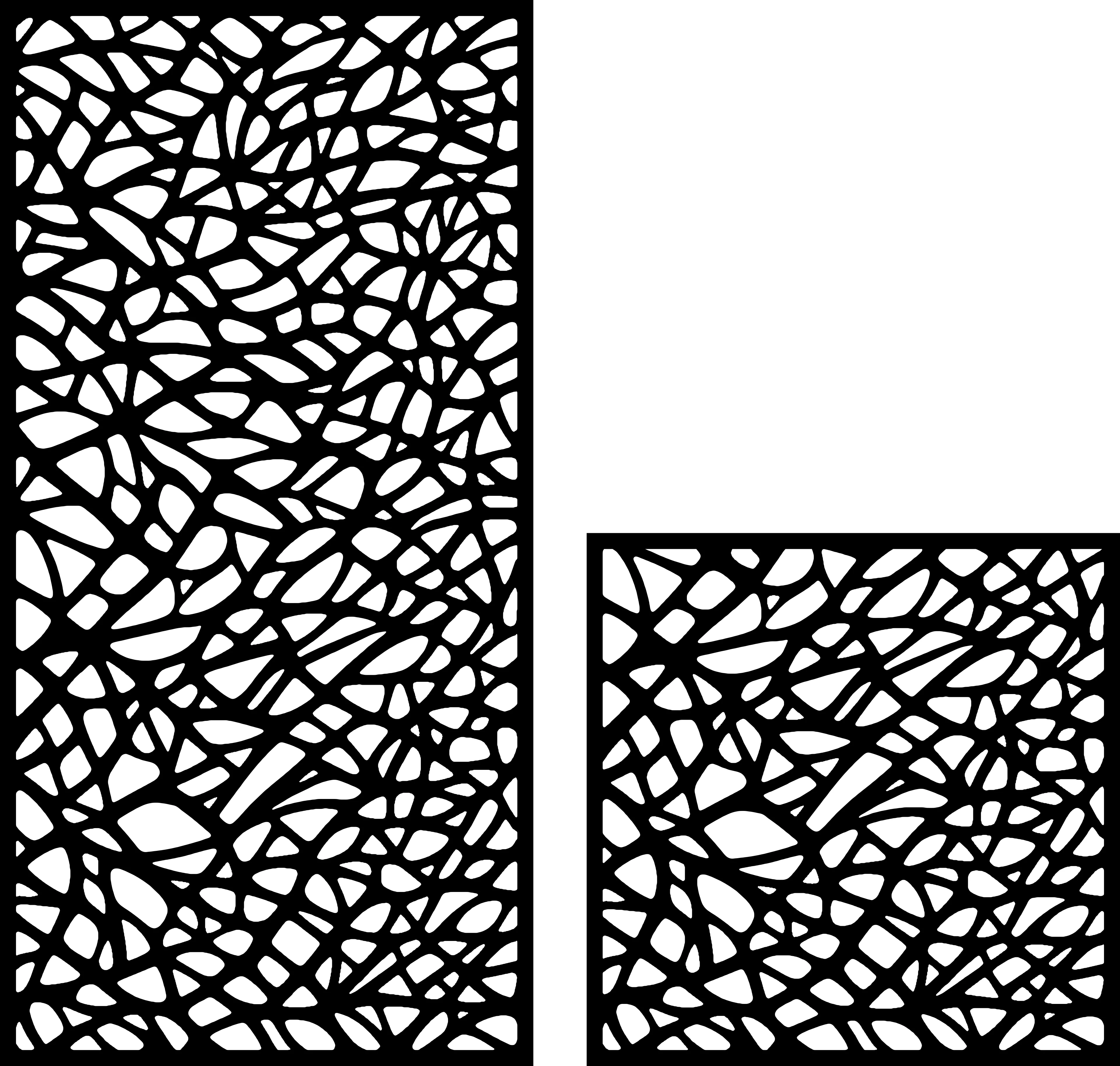
Why kerf compensation is the setting most beginners skip
If you’ve ever cut two puzzle-piece parts from the same DXF and found they were too loose or wouldn’t fit together at all, you’ve met kerf compensation — or the lack of it. Kerf is the material actually vaporized, melted, or blown away by your beam or plasma arc. It’s not a rounding error; on a 0.5mm sheet of stainless with a fiber laser it might only be 0.08mm, but on 6mm mild steel with plasma it can be 1.5mm or more. Ignore it and every interlocking joint, snug-fit slot, or nested part on your sheet will be off by that amount — sometimes enough to ruin an otherwise perfect job.
This guide covers what kerf actually is, how to measure it on your own machine, and how to dial in compensation in your DXF workflow so parts fit exactly as designed — first time, not after three test cuts.
What kerf actually is (and why it varies)
Kerf width is the width of material removed by the cutting process — essentially the “bite” the tool takes as it moves along your path. Three things drive it:
- Beam/arc/tool diameter — a fiber laser spot might be 0.1-0.3mm; a plasma torch tip can cut a kerf of 1-2mm.
- Material and thickness — thicker material needs more energy dwell time, which widens the kerf; softer/thinner material narrows it.
- Cutting parameters — speed, power, gas pressure, and assist gas type all shift kerf width even on the same machine and material.
That’s why there’s no universal number. A kerf value that’s perfect for 3mm mild steel on your fiber laser will be wrong for 1mm stainless or 10mm aluminum on a router.
Typical kerf ranges by process (starting points, not gospel)
Use these as ballpark figures, then measure your own machine — every laser and plasma table drifts slightly with nozzle wear, focus, and gas pressure.
| Process | Material/Thickness | Typical Kerf |
|---|---|---|
| Fiber laser | 1-3mm mild steel/stainless | 0.10-0.20mm |
| Fiber laser | 6-10mm mild steel | 0.20-0.35mm |
| CO2 laser | 3-6mm acrylic/wood | 0.10-0.25mm |
| Plasma (fine cut) | 3-6mm steel | 0.8-1.2mm |
| Plasma (standard) | 8-16mm steel | 1.2-2.0mm |
| CNC router | 3mm bit, MDF/wood | 3.0mm (bit diameter) |
If you cut plasma regularly, this is also worth cross-referencing with our plasma vs. fiber laser vs. CNC router comparison for how kerf interacts with edge quality on each process.
How to measure kerf on your own machine
Skip the math and just cut a test coupon — it takes five minutes and removes all the guesswork.
- Draw a simple 50mm x 50mm square in your CAD/CAM software.
- Cut it from a scrap piece of the exact material and thickness you’re working with, at your normal settings.
- Measure the cut-out square with calipers. If it measures 49.85mm instead of 50mm, your kerf is roughly 0.15mm (the beam removed 0.075mm from each side).
- Repeat on a fresh sheet edge — kerf can shift slightly as nozzle condition or focus changes over a job.
For plasma tables, cut a 100mm square instead — the larger sample makes the percentage error easier to read on a caliper, and plasma kerf is wide enough that small measurement errors matter less.
Applying compensation in your software
Once you know your kerf value, you apply it as an offset — moving your cut path either outward (for external features you want full-size) or inward (for internal holes/slots you want tight).
In LightBurn: Under Cut Settings, there’s a “Kerf” field per layer. Enter half your measured kerf value (LightBurn offsets the path by that amount on each side). If your total kerf is 0.15mm, enter 0.075mm.
In SheetCam/plasma CAM software: Kerf compensation is usually a global setting in your cut parameters, applied automatically to all outside and inside profiles in opposite directions.
In Fusion 360/CAM for routers: This is simply your tool diameter — the software already compensates because it knows the bit size, but confirm your “stock to leave” and tool diameter match your actual bit.
If your software has no kerf field: Offset the DXF geometry itself before cutting — grow outer profiles and shrink inner cutouts by half the kerf value using your CAD software’s offset/inset tool. This is more manual but works with any cutter.
Where kerf compensation actually matters most
Not every job needs precision compensation. A single decorative wall panel with no interlocking parts will look fine whether you compensate or not — a 0.1mm difference is invisible to the eye. But compensation becomes critical in a few specific cases:
Interlocking and joint designs. Anything with tabs, slots, or press-fit joints needs kerf accounted for, or parts will be too tight (won’t assemble) or too loose (wobbly, needs glue). Layered designs like our Layered Abstract Panel or geometric standoff-mount pieces depend on hole and standoff spacing being accurate to within a fraction of a millimeter.
Nested multi-part sheets. When you’re nesting dozens of parts tight together to save material, kerf compensation prevents two adjacent parts from either fusing at the edge (compensation too small, paths overlap) or leaving excess scrap gaps (compensation too generous). If you’re running nested production sheets regularly, get your kerf number locked in before you nest — it’s much easier than re-nesting after a bad batch.
Fine detail and negative space. Botanical and lace-style patterns with thin negative-space lines — like the fine veining on Botanical Leaf Panel — are the least forgiving of kerf error. A 0.3mm kerf on a design with 0.5mm-wide slots can nearly close the gap entirely, turning a clean cutout into a scorched sliver of material or a burned-through bridge.
Text and small internal cutouts. Letters with tight counters (like “e,” “a,” “o”) lose legibility fast if kerf isn’t compensated — the interior hole can shrink to nothing on small sizes.
Common kerf mistakes to avoid
- Compensating twice. If your CAM software already has a kerf field enabled, don’t also manually offset the DXF geometry — you’ll double the correction and end up further off than if you’d done nothing.
- Using the same kerf value across materials. Switching from 3mm mild steel to 3mm stainless on the same laser can shift kerf by 0.03-0.05mm — small, but enough to matter on tight-tolerance parts.
- Forgetting gas pressure changes kerf. Higher assist gas pressure blows more molten material out, often widening kerf slightly compared to lower-pressure settings at the same speed.
- Ignoring nozzle wear. A worn fiber laser nozzle or a plasma consumable near end-of-life will cut a noticeably wider kerf than a fresh one — re-measure your test coupon whenever you swap consumables.
- Applying laser kerf logic to plasma. Because plasma kerf is 10x wider than most laser kerf, small compensation habits from laser work (treating 0.1mm as negligible) will produce badly undersized parts on a plasma table.
A practical routine worth adopting
Before starting any new material/thickness/machine combination, run the 50mm test-square cut, measure it, and log the kerf value with your settings sheet (speed, power, gas, focus height). Over time you’ll build a personal kerf reference table faster and more accurate than any generic chart — including this one. Pair that habit with a solid mild steel fiber laser cutting settings chart or your stainless/aluminum equivalent, and you’ll spend far less time re-cutting parts that don’t quite fit.
If you’re building out a shop catalog with interlocking or layered pieces — multi-layer abstract art, standoff-mounted panels, or nested batches for Etsy — getting kerf dialed in early pays for itself the first time you don’t have to scrap a sheet. Browse our Abstract collection for layered and geometric designs where clean kerf compensation makes the biggest visible difference, or grab the Full Access Bundle to test your kerf settings across dozens of design styles without buying files one at a time.
Designs mentioned in this article


More articles
House Signs
10 Best DXF Designs for Modern House Signs & Address Plaques
Curated list of the 10 best DXF designs for house signs and address number plaques. Modern styles, material recommendations, install tips. Ready to cut on fiber laser or plasma.
June 8, 2026
Wall Clocks
10 Best DXF Designs for Metal Wall Clocks (Laser & Plasma Cut)
Discover the 10 best DXF wall clock designs for laser and plasma cutting, plus motor sizing, hole specs, and material tips to sell them fast.
August 27, 2026
Design Roundup
10 Best DXF Designs for Modern Fence Panels (Fiber Laser & Plasma)
Hand-picked DXF designs that look stunning as decorative fence inserts. Cut on fiber laser or plasma in 2-3 mm steel, no rescaling needed, ready in 30 minutes.
May 24, 2026