CNC Router
CNC Router Settings for DXF Files: Feeds, Speeds & Bit Selection Guide
Complete CNC router guide for cutting DXF files: bit selection, feeds and speeds charts, tabs, multi-pass depth, and common mistakes to avoid.
Why CNC Router DXF Prep Is Different From Laser Cutting
If you’ve cut DXF files on a fiber or CO2 laser and you’re now running a CNC router, the first thing you’ll notice is that a “clean” DXF for laser cutting isn’t automatically a clean DXF for routing. A laser follows a single toolpath with zero-width kerf compensation happening in software. A router has to physically shove a spinning bit — with real diameter, real flute geometry, and real cutting forces — through material. That changes how you need to think about your file before you ever touch feeds and speeds.
Three things matter most when prepping a DXF for a router:
- Closed vector paths. Open paths confuse most CAM software (Vectric, Fusion 360, Carveco) when generating pocket or profile toolpaths. Always check for gaps with a “join” or “heal” tool before importing.
- Correct offset side. Unlike laser kerf compensation (usually 0.1–0.3mm), router bit diameters range from 1/16” to 1/4”+ — so your inside/outside cut direction has a much bigger impact on final part size.
- Nested layers for multi-tool jobs. If a design has fine detail cuts and larger pocket areas, separate them onto different layers so you can assign different bits and depths in your CAM software.
Any of the Full Access Bundle designs work well as router projects once you separate detail layers this way — most files are already organized with clean, closed vector geometry, which saves real setup time compared to random free downloads.
Choosing the Right Bit for Your Material
Bit selection is 70% of getting a good edge finish on a router. Here’s what actually works:
Plywood & MDF (up to 3/4”)
- Best all-around: 1/4” up-cut spiral, 2-flute
- For chip-out-prone veneer plywood: compression bit (up-cut bottom, down-cut top) — eliminates fuzzy top edges on face-grain plywood
- Fine detail work under 1/8” wall thickness: 1/8” or 1/16” up-cut single flute
Solid hardwood (oak, walnut, maple)
- 1/4” down-cut spiral for clean top surfaces on shallow engraving/pocketing
- 1/4” up-cut for full-depth profile cuts — down-cut bits pack chips and can burn hardwood
Acrylic (cast and extruded)
- Single-flute “O-flute” bit designed for plastics — clears chips fast and prevents melting
- Never use standard wood-cutting up-cut bits on acrylic; the flute geometry is wrong and you’ll get melted, welded edges
Aluminum (thin sheet, 0.040”–0.125”)
- 2-flute solid carbide up-cut, coated (AlTiN), run slow with flood or mist coolant
- This is the one material where a router genuinely struggles compared to a fiber laser — if you’re doing regular aluminum sign work, a Fiber Laser Buying Guide is worth reading before investing more into router tooling for metal.
Feeds & Speeds Chart: Starting Points
These are proven starting points — always test on scrap before running your actual DXF file.
| Material | Bit | Spindle RPM | Feed Rate | Depth per Pass |
|---|---|---|---|---|
| 1/4” Plywood | 1/4” up-cut, 2-flute | 16,000–18,000 | 80–120 in/min | 0.125” |
| 1/2” MDF | 1/4” up-cut, 2-flute | 16,000 | 100–150 in/min | 0.15”–0.2” |
| 3/4” Hardwood | 1/4” down-cut | 14,000–16,000 | 60–90 in/min | 0.1”–0.15” |
| 1/4” Acrylic | 1/8” O-flute single | 18,000 | 40–60 in/min | full depth, 1 pass if possible |
| 1/16” Aluminum | 1/8” carbide up-cut | 10,000–12,000 | 15–25 in/min | 0.02”–0.03” |
A quick rule of thumb: chip load (feed rate ÷ RPM ÷ number of flutes) should land around 0.003”–0.006” for wood and 0.001”–0.002” for aluminum. If your edges look burnt, you’re feeding too slow for the RPM. If the bit is chattering or the DXF outline comes out oversized/rough, you’re feeding too fast.
Setting Up Tabs and Onion Skinning in Your DXF
Unlike laser cutting, where parts often just sit loose on the cutting bed, a router needs to hold the part in place mechanically during the final pass — otherwise vibration will grab the piece and ruin it (or the bit).
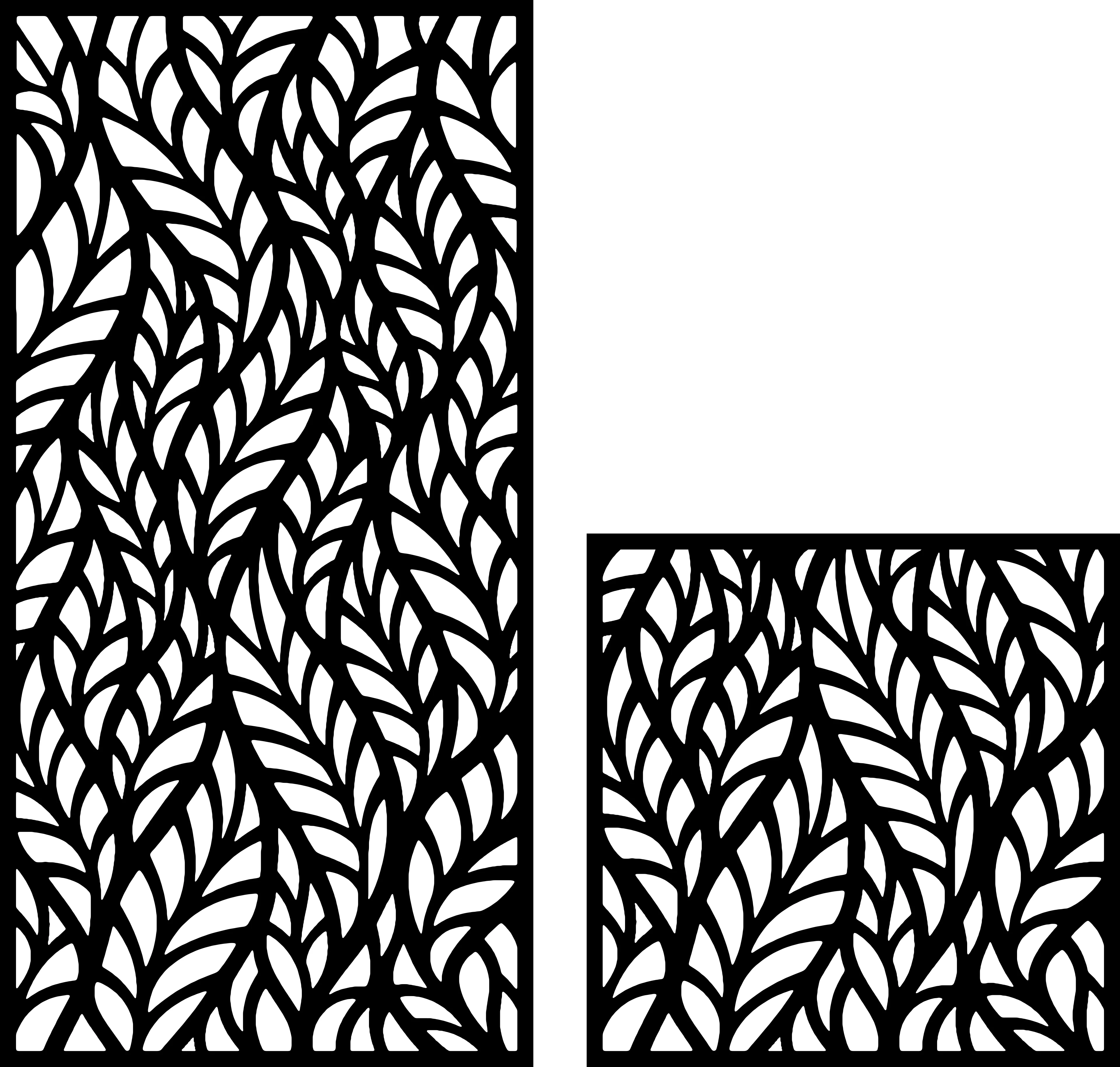
Tabs are small uncut bridges (typically 1/16”–1/8” wide, 2–4 per part depending on size) left in the toolpath that you snap or sand off after cutting. Most CAM software adds these automatically once you set tab width and height, but for intricate DXF designs with thin bridges — like detailed botanical line-art panels or fine abstract geometric patterns — manually placing tabs on the sturdiest sections of the outline prevents snapping the wrong spot and losing detail.
Onion skinning is the alternative: instead of tabs, you leave the very last 0.005”–0.02” of material uncut across the entire profile, holding the part down with light double-sided tape or a vacuum table, then peel it free by hand. This works better than tabs for delicate botanical or abstract designs where visible tab marks would ruin the piece — it leaves zero witness marks after light sanding.
Multi-Pass Strategy for Thick Sheet Material
Trying to cut 3/4” plywood in one pass with a 1/4” bit is the #1 reason routers snap bits and produce burnt, ragged edges. Split it up:
- 3/4” material: 4–5 passes at 0.15”–0.2” depth each
- 1/2” material: 3 passes at 0.15”–0.18” depth each
- 1/4” material: 2 passes at 0.1”–0.15” depth each
Your CAM software should generate this automatically once you set “depth per pass” in the toolpath parameters — you don’t need to manually duplicate layers in the DXF itself. The one thing worth double-checking: make sure your final pass depth accounts for spoilboard sacrifice (cut 0.01”–0.02” into the spoilboard) so you get a fully separated part without needing to flip and re-cut the back.
Common CNC Router Mistakes with DXF Files
- Ignoring bit diameter in tight inner corners. A 1/4” bit physically cannot cut a 90° inside corner — it will leave a radius equal to the bit radius. If your DXF has sharp inner corners that must stay sharp (like a keyway or logo notch), either switch to a smaller bit for that detail layer or add “dog-bone” relief cuts in your CAM software.
- Running climb-cut on the final pass in soft plywood. Climb milling (cutting with material feeding into the direction of bit rotation) gives a cleaner edge but can grab thin plywood and tear it. Conventional cutting on the last finishing pass is safer for delicate designs.
- Skipping a dry run. Always simulate the toolpath in your CAM software before cutting — this catches open-path errors, wrong-side offsets, and accidental double-cut lines that a laser file would have flagged differently.
- Using laser-optimized nesting. DXF files nested tightly for zero-kerf laser cutting often don’t leave enough clearance for a 1/4” router bit between parts. Add at least 0.25”–0.375” spacing when re-nesting the same file for router work.
Recommended DXF Designs to Practice On
If you’re dialing in new bits or feeds and speeds, practice on designs with a mix of long clean profile cuts and finer detail — this exposes both feed-rate issues and bit-selection issues in one test piece. Botanical line-art files like bot-02 are great for this because they combine sweeping curves (good for testing feed rate) with narrow stems and leaf tips (good for testing tab placement and bit diameter limits). Abstract geometric panels such as abs-27 are useful for testing inside-corner accuracy and multi-pass depth consistency across a large panel.
Since router work often benefits from having a wide variety of test-ready files on hand — different line weights, different amounts of negative space, different overall dimensions — grabbing the Full Access Bundle gives you enough variety to fully dial in a new bit or material setting without burning through your paid single-file budget on test cuts.
Final Thoughts
Getting good results from a CNC router on DXF files comes down to matching bit geometry to material, respecting real-world chip load numbers instead of guessing, and prepping the file with tabs or onion skinning appropriate to the design’s fragility. None of this is complicated once you’ve run it a few times — but skipping any one step is exactly how bits snap, parts blow out, and good material ends up in the scrap bin. Start conservative on feed rate, test on scrap, and scale up once your edges come out clean.
Designs mentioned in this article


More articles
House Signs
10 Best DXF Designs for Modern House Signs & Address Plaques
Curated list of the 10 best DXF designs for house signs and address number plaques. Modern styles, material recommendations, install tips. Ready to cut on fiber laser or plasma.
June 8, 2026
Wall Clocks
10 Best DXF Designs for Metal Wall Clocks (Laser & Plasma Cut)
Discover the 10 best DXF wall clock designs for laser and plasma cutting, plus motor sizing, hole specs, and material tips to sell them fast.
August 27, 2026
Design Roundup
10 Best DXF Designs for Modern Fence Panels (Fiber Laser & Plasma)
Hand-picked DXF designs that look stunning as decorative fence inserts. Cut on fiber laser or plasma in 2-3 mm steel, no rescaling needed, ready in 30 minutes.
May 24, 2026