DXF
5 Reasons Your DXF File Won't Cut Properly (And How to Fix Each One)
Troubleshooting guide for DXF files that won't cut cleanly on fiber laser, plasma, or CNC. Common kerf, scale, layer, geometry, and path direction issues — with fixes.
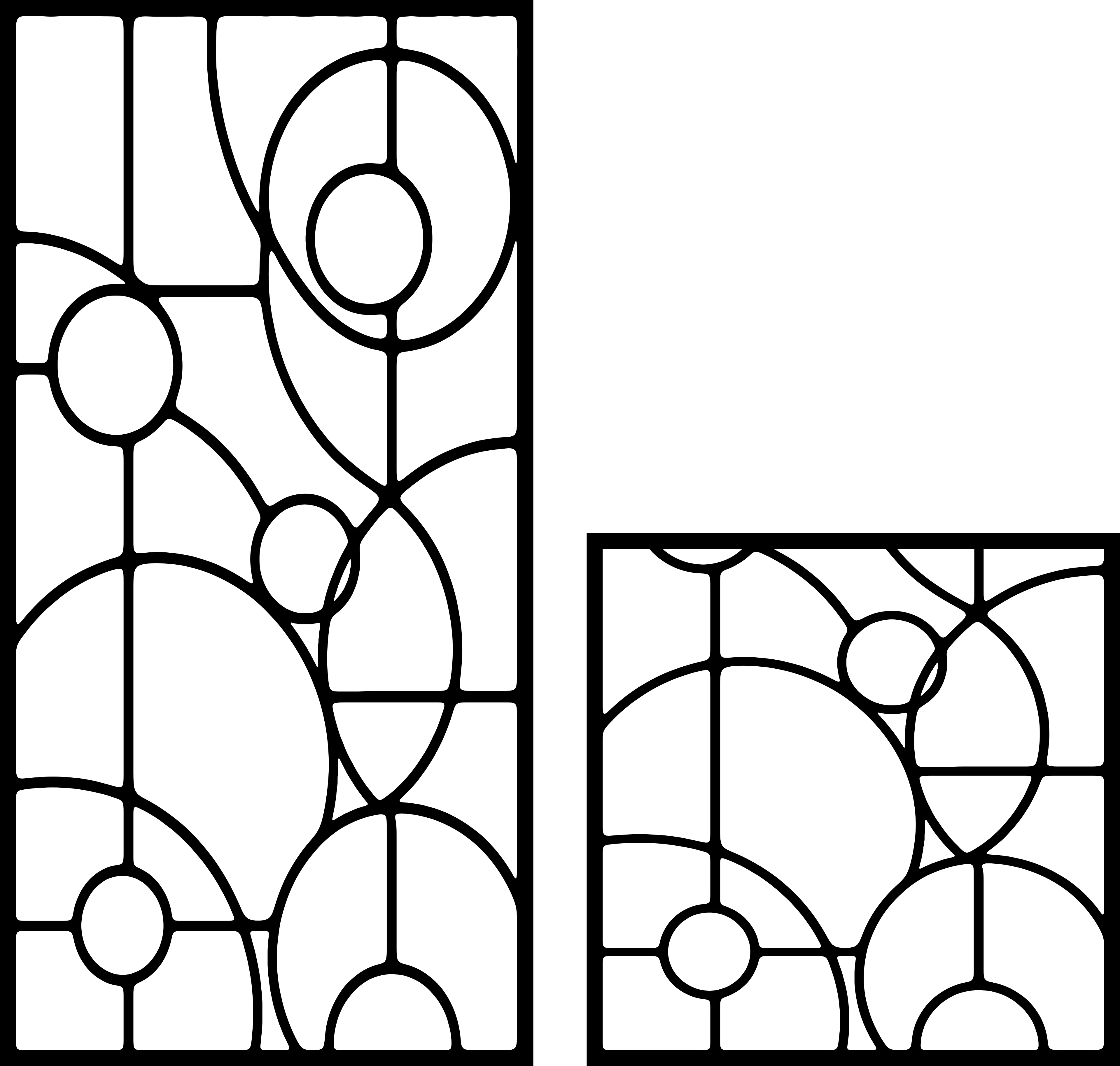
You loaded a DXF into your laser controller, hit “start”, and the result is… not what the file showed on screen. Cuts are oversized, slots don’t fit, internal features are missing, or the machine just sits there confused.
DXF cutting problems almost always boil down to 5 root causes. This guide walks through each one with a real-world symptom, a diagnosis, and a fix. By the end you’ll know exactly where to look the next time a job comes off the bed wrong.
Problem 1 — Cuts are oversized (slots too wide, holes too big)
Symptom: A 10 mm slot in the design comes out as 10.4 mm on the metal. A 5 mm hole becomes 5.3 mm. Inserts don’t fit, dowel pins are loose.
Diagnosis: Kerf compensation is wrong (or missing).
Every cutting beam has finite width. Fiber laser kerf is 0.1 – 0.2 mm. Plasma kerf is 0.8 – 1.5 mm. CNC router kerf equals the bit diameter (e.g., 3 mm). If the DXF doesn’t account for kerf, every internal cut grows wider by half the kerf on each side.
Fix:
- Open your CAM software (LightBurn, Fusion CAM, SheetCAM, RDWorks)
- Find the “Kerf compensation” or “Lead-in offset” setting
- For internal cuts (holes, slots), set offset to -0.5 × kerf width
- For external outline cuts, set offset to +0.5 × kerf width
If you don’t have CAM offset capability, edit the DXF directly in LibreCAD or Inkscape — offset each path by the correct amount before exporting.
DXFForge note: every design in our catalogue ships with 0.1 mm kerf already baked in for fiber laser. For plasma, increase your CAM offset by an additional 0.4 – 0.6 mm. For CNC router, you’ll need to add the full bit-radius offset.
Problem 2 — The whole design comes out at the wrong size
Symptom: You designed a 300 mm panel. The machine cut it at 11.8 inches. Or vice versa.
Diagnosis: Unit mismatch. DXF files don’t enforce units — the file says “100” but doesn’t say whether that’s 100 mm or 100 inches. Your CAM software guesses, and sometimes guesses wrong.
Fix:
- Open the DXF in a viewer (eDrawings or LibreCAD) and measure a known feature
- If the measurement is wrong, set the import unit explicitly in your CAM software:
- LightBurn: File → Settings → Display → Units (mm or in)
- Fusion 360: Project units in the document settings
- RDWorks: Config → System Settings → Unit
- Re-import the DXF after changing the unit setting
Pro tip: every DXFForge file ships with a labeled 100 mm reference square in the corner of the design layer. Cut a quick scribe pass on it before the full job — if it’s not 100 mm, your units are wrong.
Problem 3 — Internal cuts are missing or coming out as engraves instead of cuts
Symptom: The outline cuts fine, but the inner detail (eyes of a botanical design, holes in a fence panel) get burned/scored instead of cut through. Or they don’t appear in the toolpath at all.
Diagnosis: Layer / colour assignment is wrong.
Most laser controllers map DXF layers (or AutoCAD colours) to cut operations. If your file has all geometry on “Layer 0”, the controller doesn’t know what’s an outline, what’s an engrave, and what’s a hole.
Fix:
- Open the DXF in LibreCAD
- Group entities by purpose:
CUT_OUTSIDE,CUT_INSIDE,ENGRAVE,REFERENCE - Re-export
- In CAM software, assign each layer to the right operation (cut-through power vs engrave power)
DXFForge note: our files come pre-layered:
CUT— full power, cut-throughENGRAVE— low power, surface marking (used on a few decorative designs only)REFERENCE— non-cutting outline showing finished part dimensions (delete before sending to machine if your CAM doesn’t ignore non-mapped layers)
Problem 4 — Path direction is reversed (cuts going inside-out)
Symptom: Pierce holes show up on the wrong side of the cut line. Internal features cut as outlines instead of holes. Or the machine starts at the wrong corner.
Diagnosis: Path direction or polyline winding is incorrect.
In CAM, internal cuts should be clockwise (CW) and external outlines should be counter-clockwise (CCW), or vice-versa depending on your controller’s convention. If a path was drawn in the wrong direction, the kerf offset (Problem 1) ends up on the wrong side — internal holes shrink instead of grow, etc.
Fix:
- Open in LibreCAD or QCAD
- Select each polyline, run “Reverse direction”
- Or in CAM software, find “Auto-correct path direction” or “Optimise toolpath” and let it sort the file
- Re-export
Pro tip: when buying or downloading DXFs, look for the word “CAM-ready” or “toolpath verified” in the description. That signals the seller has already normalised direction.
DXFForge designs are all CAM-verified — internal CW, external CCW (the convention 90% of controllers expect).
Problem 5 — File has thousands of duplicate / overlapping entities
Symptom: The job preview takes forever to render. The cut takes 3x as long as estimated. The machine pauses inexplicably between identical segments.
Diagnosis: Duplicate or overlapping geometry. Common in DXFs that were converted from PDF, traced from raster images, or assembled from multiple imported sources.
Fix:
- Open in LibreCAD
- Tools → Drawing → “Remove duplicate entities”
- Tools → Drawing → “Join lines” (merges chained collinear segments into single polylines)
- Re-export
Or use the free QCAD Bonus Tools which include a more aggressive duplicate-finder.
Before/after on a typical messy file:
- Before: 4,200 entities, 18 minutes to cut
- After cleanup: 1,100 entities, 6 minutes to cut
That’s pure time saved on every job for one minute of cleanup.
The 5-minute pre-flight checklist
Before sending any DXF to your machine, run this:
- ✅ Units — measure a known feature, confirm mm vs inches
- ✅ Kerf — set CAM offset for your machine’s actual kerf width
- ✅ Layers — every entity assigned to a meaningful layer
- ✅ Direction — internal CW, external CCW (or whatever your CAM expects)
- ✅ Duplicates — purged via “Remove duplicate entities”
5 minutes saves 2 hours of wasted material.
Why DXFForge files don’t have these problems
We pre-process every file in the catalogue before it ships:
- Units always millimetres, with a labeled 100 mm reference square
- Kerf offset built in at 0.1 mm for fiber laser baseline
- Layers split into CUT / ENGRAVE / REFERENCE
- Polyline directions normalised (internal CW, external CCW)
- Duplicate entities purged
- Output tested on at least one real machine before listing
That’s the whole reason customers pay for our DXFs instead of pulling free ones off SketchFab or randomly-googled blogs. A file you can send straight to your laser is worth 30 minutes of saved work — across 77 files in our bundle, that’s 38 hours of your life back.
TL;DR
| Problem | Quick fix |
|---|---|
| Cuts oversized | Set kerf compensation in CAM |
| Wrong overall size | Set import units explicitly |
| Missing internal cuts | Assign proper layer / colour mapping |
| Cuts inside-out | Reverse polyline direction in editor |
| Duplicate entities | Run “Remove duplicates” in LibreCAD |
Bookmark this. The next time something’s off, you’ll find the cause in 3 minutes instead of 30.
Designs mentioned in this article


More articles
House Signs
10 Best DXF Designs for Modern House Signs & Address Plaques
Curated list of the 10 best DXF designs for house signs and address number plaques. Modern styles, material recommendations, install tips. Ready to cut on fiber laser or plasma.
June 8, 2026
Wall Clocks
10 Best DXF Designs for Metal Wall Clocks (Laser & Plasma Cut)
Discover the 10 best DXF wall clock designs for laser and plasma cutting, plus motor sizing, hole specs, and material tips to sell them fast.
August 27, 2026
Design Roundup
10 Best DXF Designs for Modern Fence Panels (Fiber Laser & Plasma)
Hand-picked DXF designs that look stunning as decorative fence inserts. Cut on fiber laser or plasma in 2-3 mm steel, no rescaling needed, ready in 30 minutes.
May 24, 2026